The Radon-T is the unique fitting specifically designed as the important first step when installing or roughing in a radon and moisture system during new construction.
Radon-T by RadonAway
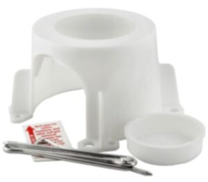
Each Radon-T comes with a kit that includes:
➕ Radon-T – Prepares for Reducing Radon in New Construction (RRNC) systems.
➕ 4 Stakes – Stabilize the T in preparation for aggregate fill and slab pour.
➕ Vent Pipe Cap – Prevents debris entry and avoids the possibility of mistaking the vent pipe sub for a utility pipe “rough in”.
➕ Set of System Labels – To clearly mark radon system vent pipes.
These instructions provide a quick guide for proper installation.
✔️PRIOR TO POURING THE SLAB
Radon-T Installation
1- In the location designated for the radon pipe rough-in, position the Radon-T on a level dirt surface.
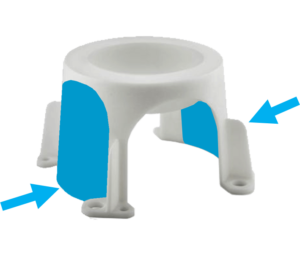
a- For optional 4-way air flow, cut out sides of the Radon-T along the indents.
b- If saddling over an internal perforated pipe loop, cut out a small top section of pipe (approximately 4 ½” x 6”) so that the Radon-T fits snugly over the pipe.
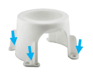
2- Using the supplied stakes, secure the Radon-T to the ground.
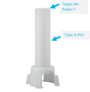
3- Glue into the Radon-T a length of 4” Schedule 40 PVC pipe. (Pipe length should allow it to extend a minimum of 6” above the finished slab.)
4- Insert the supplied Radon-T Cap into the top of the PVC pipe. Do not glue!
5- Save the 4 supplied vent pipe labels for future piping.
Site Preparation
1- Uniformly spread a layer of clean aggregate at least 4” thick. The aggregate should be sized to pass through a 2” sieve but not through a ¼” sieve. (Where gravel is not available, substitute a 4” layer of sand covered by geotextile drainage matting.)
2- Install vapor barrier (minimum 6 mil or 3 mil cross- laminated) on top of the aggregate. The barrier should cover the entire floor area and seams should have a 12” minimum overlap.
✔️AFTER POURING THE SLAB
1- Fill all large openings in the slab. Seal perimeter and all joints in the concrete, cap sump pit openings. Floor drains should be trapped or routed to daylight with non-perforated pipe.
2- Remove the Radon-T cap. Connect and glue PVC riser with appropriate PVC fittings.
3- Route 3” or 4” PVC radon vent pipe through the structure.
💭Design reminders
Pipe termination must extend at least 12” above the roof surface and at least 10 ft from doors and other openings (including operable skylights) that are less than 2 ft below the termination point. |
4- Install a wired electrical outlet (120volt AC) next to the anticipated radon fan location.
5- Affix one supplied radon label to the pipe at each level of the structure (e.g., basement, first floor, etc.). Be sure the airflow arrows on the labels point away from the slab.
Source: RadonAway.com

